
1.1. HAZOP
1.1.1. Description and Purpose
1.1.1.1.
Hazard and Operability (HAZOP) studies methodology was developed by ICI in the United Kingdom during the early 1960s as it required a more formalised technique for critical analysis of plant design and operation. They had reviewed the techniques being used in various parts of the company, and concluded that their quality was too heavily dependent on the people who made up the study teams. They asked the Method Study experts in the company to devise a formal review technique, and to hand it over to the engineers for use in new plant reviews. The basic HAZOP methodology was then devised by the team to fulfil these requirements.
1.1.1.2.
After the Flixborough disaster, where 28 people died, the technique started to be widely used within the chemical process industry. The approach was then adopted by the petroleum industry where there was another obvious potential for major disaster. The food and water industries subsequently employed HAZOP although more for contamination analysis rather than explosions or chemical releases.
1.1.1.3.
The HAZOP procedure involves a multi-disciplinary team who has substantial experience of the system or design to be studied. The team consider taking a full description of a process and systematically question every part of it to establish how deviations from the design intent can arise. For each credible deviation the group considers possible causes and consequences and decides if additional safeguards should be recommended when consequences are found to have a negative effect upon the safe and efficient operation of the plant. This examination of the design is structured around a specific set of guidewords, which ensure complete coverage of all possible problems whilst allowing sufficient flexibility for an imaginative approach.
1.1.1.4.
Each HAZOP has a set of objectives, which are particular to that study and are decided as near to the beginning of the study as possible. However, there are four overall aims for any HAZOP:
- To identify all deviations from the way the design is expected to work; their causes, and all the hazards and operability problems associated with these deviations.
- To decide whether action is required to control the hazard, or the operability problem, and if so to identify the ways in which the problem can be solved.
- To identify cases where a decision cannot be made immediately and to decide on what information or action is required.
- To ensure that actions decided upon are followed through.
1.1.1.5.
The HAZOP technique is very versatile, and can be applied to both continuous and batch processing. Generally, the HAZOP methodology is intended for use on a continuously operating system, although in concept it is equally applicable to a batch process. In fact, if one considers the start-up and shutdown procedures of a continuous process plant, it can be shown that it is nothing more than a batch plant with a long reaction cycle. However, there are several important differences in the HAZOP procedure, such as, data required, preparation time, and study time that must be understood in order to plan and carry out such a study. These differences apply when the complete process unit is operated batchwise and also when there is only a single batch process step in a large continuous unit.
1.1.1.6.
In addition to the normal data collected, it is necessary to have details of the sequence of operations for the batch process. This may be in the form of an operating procedure for manually operated equipment, or as a sequence flow chart for an instrument-or computer-controlled system. Important elements of this information are:
- All steps must be specified, and the process state for each defined (e.g. fill line open, stirrer running etc.).
- Any interlock operating during the step must be known (e.g. solenoid operation removes signal from a valve, which must be closed).
- The condition necessary to move to the next step must be known (e.g. time from beginning of step, temperature set point reached etc.).
- Details of any ’watchdogs’ must be given (e.g. if action is not completed within 30 minutes an alarm is generated or processing stops).
1.1.1.7.
If a batch process is converted to continuous, it will almost always result in a system with more main plant items. It is, therefore, almost always true that the study time required will be significantly greater for a batch system than for a similar Process and Instrumentation Diagram of a continuous process.
1.1.2. When It Might be Used
1.1.2.1.
As mentioned, HAZOP is primarily used for identifying safety hazards and operability problems of continuous process systems and for the review of procedures and sequential operations. Overall, HAZOP has become a standard tool across a variety of sectors (e.g. petrochemical, offshore) and procedural HAZOP is widely used for both simultaneous operations and the assessment of evacuation systems. However, other HAZID techniques may be more efficient for many marine hazards depending upon the experience and availability of the team, the phase of the design, the information available, etc.
1.1.3. Advantages, Disadvantages, and Limitations to The Defence Sector or The Particular Domain
1.1.3.1.
Advantages
- It is widely-used and its advantages and disadvantages are well understood and well known
- It uses the experience of operating personnel as part of the team
- It is systematic and comprehensive, and should identify all hazardous deviations from the design intent and also from the operability perspective
- It is effective for both technical faults and human errors. It recognises existing safeguards and develops recommendations for additional ones
- The team approach is particularly appropriate to requiring the interaction of several disciplines or organisations
- It provides a means of assessing hazards before a system becomes operational
- The method aids the derivation of corrective and preventive measures that may be incorporated into the system.
1.1.3.2.
Disadvantages
- Its success depends on the facilitation of the leader and the knowledge of the team. It is vital that the HAZOP leader understands the batch process in some detail before the study begins. Otherwise, he/she may be inefficient during the team study if most other team members understand the process
- It is optimised for process hazards, and needs modification to cover other types of hazards
- One procedure for a batch HAZOP is called 'step by step'. In this procedure each batch process step is taken in turn, and the guideword study of the system is carried out for that step. After completing the study for the first process step the other steps are taken in sequence, using the same technique. The technique can be very repetitive but it is necessary in order to be systematic and complete
- It is a rigorous analysis tool and therefore requires development of procedural descriptions and access to detailed design and operational information which are often not available in appropriate detail. However, the existence of these documents will benefit use of the technique
- Documentation is lengthy (for complete recording)
- The method is labour intensive and time consuming in that many subject matter experts from across various disciplines are required
- The method may not be able to provide adequate design solutions to the human error problems it highlights
- It focuses on identifying single failures. Not all combinations of events – more detailed techniques such as Fault Tree Aanalysis may be needed
1.1.4. Sources of Additional Information
1.1.4.1.
A list of additional information (e.g., Standards, textbooks, and websites) includes but is not limited to:
- Def Stan 00-055: Requirements for Safety of Programmable Elements (PE) in Defence Systems - Requirements and Guidance
- Petroleum and Natural Gas Industries – Offshore Production Installations – Guidelines on Risk Assessment (ISO17776:2000)
- IEC 61882: Hazard and Operability Studies (HAZOP Studies) – Application Guide
- Risk-Based Decision Making (RBDM) Guidelines
- Human Factors Integration in ATM System Design
1.1.5. Additional Comments
1.1.5.1.
A list of software programs (e.g., Computer tools and related techniques) includes but is not limited to:
1.1.6. A Simple Example of a HAZOP
1.1.6.1.
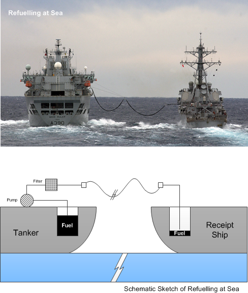
Fuel oil is transferred from a tanker to a ship as shown in Figure 1. A simple sketch describing part of the system is shown in Figure 2. In this example we shall apply the HAZOP technique to the equipment shown. We are interested in safety hazards and environmental aspects.
1.1.6.2.
Fuel is removed from one of the fuel storage tanks on the supply vessel by pump and transferred to the fuel storage tank on the receiving ship via permanent pipework and a flexible hose connection. There are manual valves on the suction and discharge to the transfer pump and also a filter to prevent solids from being transferred. There is also a manual valve at the delivery on the receiving ship. Couplings are provided at each end of the hose to enable quick connection.
1.1.6.3.
The fuel is at ambient temperature; the pressure is negative static head at the pump suction and 3 barg maximum at pump discharge. The storage tanks are at atmospheric pressure with capacities of 50 and 20 m3 respectively for the tanker and receiving ship. Fuel flow rate is 500 litres per minute. It is assumed that level measurement in the tanks is by manual dipping and that the pump is started and stopped using a local pushbutton. A procedure is in place for correct configuration of the pipework and equipment and subsequent transfer of the fuel.
1.1.6.4.
An example of the completed logsheet for this HAZOP study is shown in the Table below.
1.1.6.5.
| Project: Fuel Transfer System | Revision: 0 | Node: 001 | Page: 1 |
| Date: | Time: | ||
| Session: 0 | Team: | ||
|
Node Description: The hose connections from the tanker to the ship tank connection pipe including the pump, filter and manual valves on the pump inlet and outlet. |
Leader:
|
Recorder: | |
| Organisation: XYZ | |||
| Location: Various | |||
|
Design Intention: To transfer fuel from the tanker to the ship tank via the installed pump. |
P&ID's | Rev #'s | |
|
Normal Process Conditions (Range): Temperature: Ambient Pressure: Negative static head from tanker, 3 barg maximum at pump discharge Flow rate: 500 litres per minute |
|||
| Team Members: | |||
1.1.6.6.
| Project: Fuel Transfer System | Node: 001 | Page: 2 | |||
| Node Description: The hose connection from the tanker to the ship tank including the pump and manual valves on the pump inlet and outlet. | |||||
| Guideword/Deviation | Causes | Consequences | Safeguards | Rec# | Recommendation |
| No Flow | Manual valve on pump inlet closed | No transfer of fuel. Pump starved of liquid, which could cause mechanical damage and possible leakage from the pump to sea. Possible fire if there is an ignition source. |
Operators knowledge and training. Local stop which will be used by operator if pump leaks or is noisy. |
R1 | Provide low level / dry running cut out for the pump to prevent pump damage on loss of suction. |
| Manual valve on pump outlet closed | No transfer of fuel. Pumps runs against a closed discharge, which could cause overheating, mechanical damage and leakage if left for too long. | As before. Also this valve is normally kept open. | R2 | Develop a checklist for use by the operator when carrying out tanker transfers. Ensure checks of manual valve positions are included in this checklist for all stages of fuel delivery. | |
| Line or filter blocked. | As above. | As above. Line or filter blockage is unlikely since fuel delivered is clean. | |||
| Reverse Flow | Backflow of fuel when disconnecting tanker hose at ship due to siphoning. | Spillage of fuel on ship with potential spillage to sea and fire hazard. | Operator closes manual valve before disconnecting hose. | R3 | Install a non-return valve in the line to the ship fuel tank. |
| Operator could be splashed with fuel when disconnecting hose. | Operator wears gloves and goggles. | ||||
| More Flow | Tanker hose or transfer pipe rupture. | Discharge of fuel from hose or pipe to sea causing environmental pollution. Potential for fire if there is a source of ignition. |
Hoses and pipework are rated for 7 barg pressure. Maximum pump pressure is 3 barg. |
R4 | Develop oil spill containment response procedures and check suitability of hardware for spillage cleanup. |
| R5 | Review adequacy of the fire fighting equipment on the ship. | ||||
1.2. Version Control
1.2.0.1.
Version 3.0 to 3.1 Uplift
Links within Sources of Additional Information and Additional Comments have been updated.
Version 2.3 to 3.0 Uplift
Major uplift from the Acquisition System Guidance (ASG) to online version.