
1.1. Fault Tree Analysis
1.1.1. Description and Purpose
1.1.1.1.
Fault-Tree Analysis (FTA) is a graphical binary logic top-down technique that is used to describe how a specific unwanted event in a system may be caused by the effects of a single failure or combination of failures. The specific unwanted event, such as an accident or explosion, is known as the “top event”, where definition is critical to the success of this type of analysis. The fault tree is then constructed by relating sequences of events which individually or in combination could lead to the top event. The linkages between faults are represented by Boolean logic gates, such as AND or OR gates, which serve to permit or inhibit the flow of fault logic up the tree. These symbols denote the relationship of the input events required for the output event. The tree is constructed by deducing in turn the preconditions for the top event and then successively considering the next level of events, and the next, until the basic causes are identified.
1.1.1.2.
A fault tree can be used quantitatively to permit frequency or probability of the top event to be calculated or it can be used qualitatively to identify combinations of basic events that are sufficient to cause the top event; these are known as ‘cut sets’. Cut sets are identified using the technique “Minimal Cut Set Analysis” which assigns a unique label to every base event on the tree and shows all possible ways in which these can combine to lead to the major hazard event. These are often shown as letter combinations, for example, A, AB, ABCD, CDFGH. These are known as Single Event Cut Sets, Two Event Cut Sets, etc.
1.1.1.3.
The significance of these is that single or two event cuts imply no or little safeguarding between the initiating event and the top event, whereas 4 and 5 event cut sets do have multiple redundancy. There are rules of thumb appropriate for major hazards that single or 2- event cut sets require additional mitigation / safeguarding, whereas 5 event cut sets and higher are probably adequate. Three and 4 event cut sets may require additional evaluation. Factors for evaluation include both the number of safeguards and their quality or reliability.
1.1.1.4.
Unlike FMEA, the technique has the flexibility to allow the consideration of human errors, as well as permitting the modelling of equipment failures and external conditions, which can lead to an accident.
1.1.2. When It Might be Used
1.1.2.1.
FTA is generally applicable for almost every type of system-level risk assessment application, but is used most effectively to address the fundamental causes of specific identified accidents likely to be dominated by relatively complex combinations of events. It can be used to determine the root causes that could lead to an accident so enabling preventative or mitigative measures to be identified reducing the likelihood of the event.
1.1.3. Advantages, Disadvantages, and Limitations to The Defence Sector or The Particular Domain
1.1.3.1.
Advantages
- The technique is widely used and well accepted and can be used for cross-discipline system analysis
- It is suitable for considering the many hazards that arise from a combination of adverse circumstances
- It allows for the identification of common mode or common cause failures which may not be apparent when considering sub-systems in isolation
- It is often the only technique that can generate credible likelihoods for novel, complex systems
- Human errors can be included in the analysis
- It can be used both qualitatively and quantitatively depending on what is required from the analysis
- It a clear and logical form of presentation to non-specialist users provided an appropriate of the tree is used.
1.1.3.2.
Disadvantages
- The diagrammatic format discourages analysts from stating explicitly the assumptions and conditional probabilities for each gate. This can be overcome by careful back-up text documentation.
- FTA can be come time-consuming and complicated for large systems
- The technique examines only one specific top event. Additional FTAs must be developed to analyse other top events
- Analysts may overlook failure modes and fail to recognise common cause failures (i.e., a single fault affecting two or more safeguards) unless they have a high level of expertise and work jointly with the operator
- Manual FTA assumes all events are independent however the more sophisticated computer software packages can cater for the combination of events
- Due to its wide use there can be temptation to read across data from ARM or ILS projects where, for example, the fault-tree technique has been used. As a consequence, the safety perspective can be lost as human error has been excluded and the focus has been solely on determining faults and on not on more far-reaching safety issues
1.1.4. A Simple Example of a Fault Tree
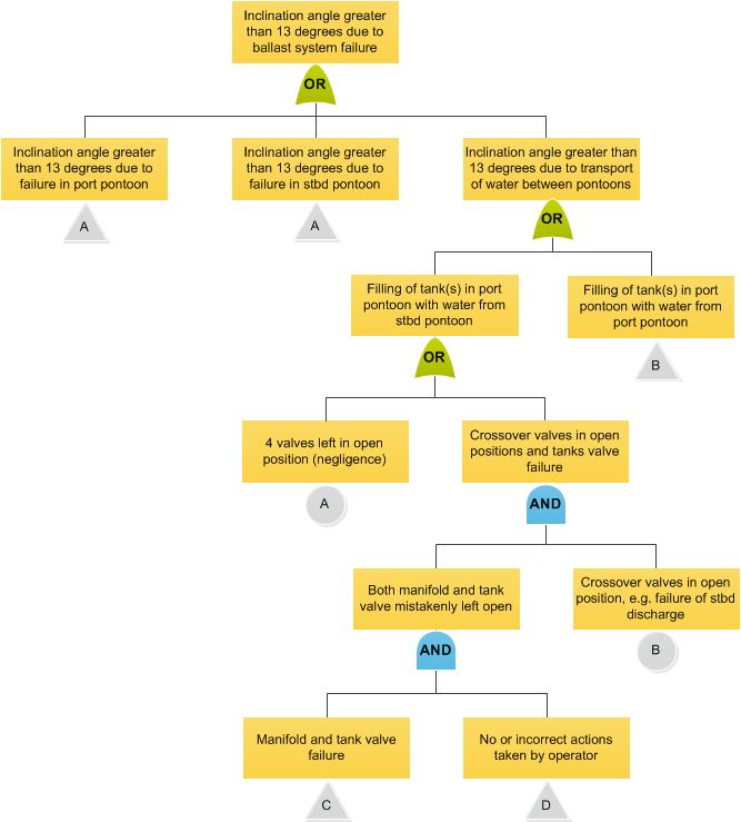
1.1.4.1.
The example below is a fault-tree of ballast system failures.
1.1.5. Sources of Additional Information
1.1.5.1.
A list of additional information (e.g., Standards, textbooks, and websites) includes but is not limited to:
1.1.6. Additional Comments
1.1.6.1.
A list of software programs (e.g., Computer tools and related techniques) includes but is not limited to:
1.2. Version Control
1.2.0.1.
Version 3.0 to 3.1 Uplift
Links within Sources of Additional Information and Additional Comments have been updated.
Version 2.3 to 3.0 Uplift
Major uplift from the Acquisition System Guidance (ASG) to online version.